Overview
- Brief Narrative
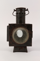
- Railroad switch stand with a signal lantern, weighted arm, and base used at the railroad station in Sobibor, Poland, before and during World War II. When the weighted arm is lifted, a section of track, the switch, is pulled and shifts into a different position. This simultaneously turns the lantern to display a signal window that corresponds to the switch position. In 1941, German authorities began preparations for Operation Reinhard, the systematic extermination of all Jews living in German occupied Poland. In March 1942, SS and police authorities began construction of Sobibor killing center, the second of three such facilities. The center was built in a wooded area near the town of Sobibor, along a spur of the existing Chelm-Wlodawa rail line. In May, regular train transports of Jewish people from German occupied regions began arriving at the center. The prisoners were herded off the trains and forced into a receiving area where they were stripped of their possessions, forced to undress, and pushed into rooms labeled as showers where they were killed with poison gas. In November 1943, the guards shot the remaining prisoners and dismantled the killing center. It is estimated that between 200,000 and 250,000 Jews were murdered at Sobibor.
- Date
-
use:
after 1900-before 1946
- Geography
-
use:
Sobibor (Poland)
- Credit Line
- United States Holocaust Memorial Museum Collection, Gift of the Polish Railroad Authority
- Contributor
-
Original owner:
Polish Railroad Authority
Physical Details
- Classification
-
Tools and Equipment
- Category
-
Equipment
- Object Type
-
Railroad switches (lcsh)
- Physical Description
- The railroad switch stand is used to pull a section of the track, the switch, into a different position and turn the attached lantern as a corresponding signal window. The signal lantern is attached to the top of a rod extending from a base that has a Y shaped bracket attached to a weighted attachment lever that extends from the back of the base. When the weight is lifted, the Y shaped bracket turns and pulls the switch into a different position. The same motion also rotates the lantern and alters which signal window is being displayed. The components are assigned for cataloging purposes only.
a. Large, rectangular, black painted, cast iron lantern with 4 panes of opaque white glass set into cutout windows. The front and back windows are rectangular, the left is circular, and the right is a diagonal, upward pointing arrow. The left side of the hinged front door is secured with a latch. On top is a cylindrical chimney with a ring of circular vent holes and a convex, circular lid. The base is flat with 5 mounting holes. There are slots on the interior of each window to mount the glass panes. The back pane is broken in half. The right pane (b) is detached and broken.
b. Thin, opaque white, arrow shaped, railroad lantern window pane broken into 6 pieces. It has 5 straight sides, 2 forming the point at one end. The pane was removed from railroad lantern (a.)
c. Large, heavy, circular, black, cast iron weight at the end of a straight attachment lever. At the other end is a U shaped bracket, which connects to a short support rod on the switch stand base (d.) Near the outer edge of the weight is a short, cylindrical handle used to lift the bar and switch the signal. There are traces of white paint on the weight.
d. Heavy, black, cast iron railroad switch base with a rectangular bottom that tapers toward the top and curves forward. There are 2 thick, movable adjustment rods: a horizontal 1 at the back with a Y shaped extension and a vertical 1 at the front with a square mounting plate on top for lantern (a.) - Dimensions
- a: Height: 16.750 inches (42.545 cm) | Width: 9.625 inches (24.448 cm) | Depth: 12.875 inches (32.703 cm)
b: Height: 12.875 inches (32.703 cm) | Width: 5.750 inches (14.605 cm) | Depth: 0.125 inches (0.318 cm)
c: Height: 25.750 inches (65.405 cm) | Width: 9.750 inches (24.765 cm) | Depth: 9.875 inches (25.083 cm)
d: Height: 15.750 inches (40.005 cm) | Width: 15.750 inches (40.005 cm) | Depth: 17.000 inches (43.18 cm) - Materials
- a : cast iron, glass, paint
b : glass
c : cast iron, paint
d : cast iron, paint - Inscription
- a. side, below arrow, white paint : 2
Rights & Restrictions
- Conditions on Access
- No restrictions on access
- Conditions on Use
- No restrictions on use
Keywords & Subjects
Administrative Notes
- Legal Status
- Permanent Collection
- Provenance
- The railroad switch stand was donated to the United States Holocaust Memorial Museum in 1990 by the Polish Railroad Authority.
- Funding Note
- The cataloging of this artifact has been supported by a grant from the Conference on Jewish Material Claims Against Germany.
- Record last modified:
- 2022-07-28 18:21:24
- This page:
- https://collections.ushmm.org/search/catalog/irn3499
Download & Licensing
In-Person Research
- By Appointment
- Request 21 Days in Advance of Visit
- Plan a Research Visit
- Request to See This Object
Contact Us
Also in Polish Railroad Authority collection
The collection consists of railroad signal lanterns, a switch lamp, a station telephone, and station signs used in the daily operations of the railroads in Poland before and during the Holocaust.
Date: after 1900-before 1946

Railroad signal lantern with a reflector from Sobibor railroad station
Object
Enclosed, oil burning, railroad signal lantern with a reflector used at the railroad station in Sobibor, Poland, before and during World War II. The lantern reflected light in a pre-determined manner to convey information about trains and rail lines. In 1941, German authorities began preparations for Operation Reinhard, the systematic extermination of all Jews living in German occupied Poland. In March 1942, SS and police authorities began construction of Sobibor killing center, the second of three such facilities. The center was built in a wooded area near the town of Sobibor, along a spur of the existing Chelm-Wlodawa rail line. In May, regular train transports of Jewish people from German occupied regions began arriving at the center. The prisoners were herded off the trains and forced into a receiving area where they were stripped of their possessions, forced to undress, and pushed into rooms labeled as showers where they were killed with poison gas. In November 1943, the guards shot the remaining prisoners and dismantled the killing center. It is estimated that between 200,000 and 250,000 Jews were murdered at Sobibor.

Painted composition board sign from Belzec railroad station
Object
Painted composition board sign used to identify the railroad station in Belzec, Poland, before and during World War II. In early 1941, German authorities began preparations for Operation Reinhard, the systematic extermination of all Jews living in German occupied Poland. In November, SS and police authorities began construction of Belzec killing center. The center was built near the town of Belzec, along a siding of the existing Lublin-Lvov rail line. In March 1942, regular train transports of Jewish people from German occupied regions began arriving at the center. The prisoners were herded off the trains and into a receiving area where they were stripped of their posessions, forced to undress, and pushed into rooms labeled as showers where they were killed with poison gas. In spring 1943, Belzec was decommissioned and dismantled. The authorities planted trees and flowers to camouflage the area. A farm house was constructed for a local family to serve as wardens and prevent scavenging locals from unearthing the mass graves. It is estimated that between 500,000 and 600,000, mostly Jews, were murdered at Belzec.
Hand crank, table top telephone from Sobibor railroad station
Object
Table top, crank handle telephone used at the railroad station in Sobibor, Poland, before and during World War II. In 1941, German authorities began preparations for Operation Reinhard, the systematic extermination of all Jews living in German occupied Poland. In March 1942, SS and police authorities began construction of Sobibor killing center, the second of three such facilities. The center was built in a wooded area near the town of Sobibor, along a spur of the existing Chelm-Wlodawa rail line. In May, regular train transports of Jewish people from German occupied territory began arriving. Prisoners were herded off the trains into a receiving area where they were stripped of their possessions, forced to undress, and pushed into rooms labeled as showers where they were killed with poison gas. In November 1943, the guards shot the remaining prisoners and dismantled the killing center. It is estimated that between 200,000 and 250,000 Jews were murdered at Sobibor.
Painted steel sign from Sobibor railroad station
Object
Painted metal sign used to identify the railroad station in Sobibor, Poland, before and during World War II. In 1941, German authorities began preparations for Operation Reinhard, the systematic extermination of all Jews living in German occupied Poland. In March 1942, SS and police authorities began construction of Sobibor killing center, the second of three such facilities. The center was built in a wooded area near the town of Sobibor, along a spur of the existing Chelm-Wlodawa rail line. In May, regular train transports of Jewish people from German occupied regions began arriving at the center. The prisoners were herded off the trains and forced into a receiving area where they were stripped of their possessions, forced to undress, and pushed into rooms labeled as showers where they were killed with poison gas. In November 1943, the guards shot the remaining prisoners and dismantled the killing center. It is estimated that between 200,000 and 250,000 Jews were murdered at Sobibor.
Lantern from Belzec railroad station
Object
Railroad lantern used at the railroad station in Belzec, Poland, before and during World War II. In early 1941, German authorities began preparations for Operation Reinhard, the systematic extermination of all Jews living in German occupied Poland. In November, SS and police authorities began construction of Belzec killing center. The center was built near the town of Belzec, along a siding of the existing Lublin-Lvov rail line. In March 1942, regular train transports of Jewish people from German occupied regions began arriving at the center. The prisoners were herded off the trains and into a receiving area where they were stripped of their possessions, forced to undress, and pushed into rooms labeled as showers where they were killed with poison gas. In spring 1943, Belzec was decommissioned and dismantled. The authorities planted trees and flowers to camouflage the area. A farm house was constructed for a local family to serve as wardens and prevent scavenging locals from unearthing the mass graves. It is estimated that between 500,000 and 600,000, mostly Jews, were murdered at Belzec.


